Model ASE-2 AM Stereo Exciter

FCC Type Acceptance Number DK7ASE-2
Features
- High stereo separation, low distortion
- Crystal controlled carrier frequency
- Standard TTL RF output
- Optional high level RF output
- All controls front panel accessible
|
- Balanced 600 ohms audio input and output
- Optional synchronous transmitter operation
- Single rack unit equipment height
- AM expansion band compatible
- Rear panel carrier test output
|
Introduction
The Model ASE-2 AM Stereo Exciter provides high performance C-QUAM® stereo signals with superior separation and extremely low distortion. The high quality and low cost ASE-2 Exciter converts your monophonic AM station to a more competitive and better sounding AM stereo station.
Unlike the early days of FM stereo broadcasting when stereo sound was an exciting new development, today's listeners expect to hear stereo. Virtually all sound recordings and FM broadcasts are now stereo. Also, all compact disks are stereo and many television stations have converted from monophonic to stereo broadcasting. It is important for AM stations to upgrade to AM stereo broadcasting to achieve the standard of excellence expected by today's listeners.
The Delta Electronics Model ASE-2 AM Stereo Exciter converts your station's transmitter to AM stereo operation as easily as possible. All switches and controls used during the installation process are clearly labeled and are readily available on the front panel. The ASE-2 technical manual contains a thorough description of installation procedures and adjustments to assist the broadcast engineer. Conservative design practices ensure that the ASE-2 will provide many years of trouble free operation.
Description
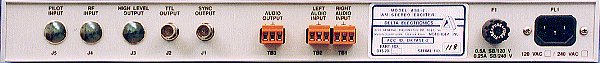
The Model ASE-2 AM Stereo Exciter converts a broadcast transmitter operating in the medium wave band (530 kHz to 1700 kHz) from monophonic to stereo operation using the C-QUAM standard. Balanced audio inputs from the audio processing equipment connect to the Left Audio Input and the Right Audio Input connectors. The Audio Output connector provides a balanced audio signal for the transmitter's modulator. This is the main channel audio (left channel plus right channel or L+R) which amplitude modulates the carrier inside the transmitter just as in monophonic operation. The front panel SEP control sets the level of this audio for best stereo separation.
The ASE-2 generates an RF signal to replace the transmitter's crystal oscillator. This RF signal is phase modulated and contains the stereo subchannel (left channel minus right channel or L-R) information. The RF signal is available in two forms, a TTL level square wave from the TTL OUT connector or an optional, adjustable high level square wave from the High Level Output connector. The RF output employed is determined by the transmitter's requirements. The ASE-2 has equalization filters and delay circuits which control the properties of the phase modulated RF signal to compensate for transmitter characteristics. When these controls are correctly adjusted, the transmitter produces accurate C-QUAM AM stereo modulation.
The front panel has a removable, clear plastic cover to prevent inadvertent misadjustments of controls. Removal of this plastic cover accesses the setup controls. The Model ASE-2 is specifically designed so that all switches and controls are adjustable from the front panel. Thus, installation and testing may be done with the ASE-2 permanently installed in a standard equipment rack.
The figure below is a simplified block diagram of the AM stereo transmission system which illustrates the basis for C-QUAM AM stereo generation. Not shown are equalization filters, delay circuits and pilot circuits. The left and right channel audio inputs are summed to produce a main channel (L+R) audio signal for the transmitter's amplitude modulator. This amplitude modulation is the same as monophonic modulation so that envelope detectors in monophonic radios are fully compatible. The L+R audio signal also modulates an in-phase (0º) RF carrier (I Amplitude Modulator). The L-R subchannel audio signal, generated by subtracting the right channel from the left channel, suppressed carrier modulates a carrier at the same frequency but with a 90º or quadrature phase shift (Q Suppressed Carrier Modulator). The suppressed carrier modulation is amplitude modulation with the carrier frequency removed. These two RF signals are summed to produce a quadrature amplitude modulated (QUAM) signal. The QUAM signal is passed through an amplitude limiter to produce a phase modulated signal with constant amplitude. This phase modulated RF signal, containing the subchannel information, replaces the crystal oscillator in the transmitter. The transmitter amplitude modulates the phase modulated RF signal to produce C-QUAM AM stereo transmission.
Configurations
The Model ASE-2 has three options which must be specified when ordered. The first option is the AC line voltage specification. Standard line voltages are 100, 120, 200 and 240 VAC. The second option is for high level output. The standard unit provides a TTL level RF output. Transmitters with tube type oscillator circuits generally require the high level output option which provides a square wave output of up to 35 Vp-p into 50 or 75 ohms. The third option is the synchronous transmitter operation where a carrier reference signal and a pilot reference signal are externally supplied to their respective connectors on the rear panel of the ASE-2 Exciter.
Options and Accessories
The ASM-1 AM Stereo Modulation Monitor helps maintain and ensure optimum AM stereo broadcast system performance. The ASM-1 incorporates a high performance C-QUAM decoder to demodulate the RF sample. The distortion and noise levels of the monitor are sufficiently low that the measurements made of the various performance characteristics will be reflective of the limits of the broadcast transmitter/stereo encoder performance. The monitor provides all the demodulated signals necessary for precision performance tests when used with standard audio measurement equipment. The signals available on the rear panel of the monitor include L+R, L-R, Envelope Detector Output, and Left and Right audio (both balanced and unbalanced). The 25 Hz pilot tone is also available. The front panel meters display positive and negative L+R, L-R, L and R modulation levels. Peak flashers indicate -100%, +125%, L-R 100% and High Angle modulation conditions. Thumbwheel controlled positive and negative peak modulation flashers may be set to flash at any level of modulation. Remote outputs for the modulation meters and the thumbwheel controlled peak flashers are accessible through rear panel connectors.
The Sample Transmitter Unit is an external unit that generates a low level C-QUAM signal for closed loop testing with a stereo modulation monitor. The sample transmitter unit produces an AM stereo signal at 0.3 Vp-p into a 50 ohm load.
The Stereo Switch Box allows easy switching between main channel, subchannel and single channel operation for test and alignment of the transmitter and the exciter during installation and maintenance.
The High Purity Filter is an optional external unit that filters the high level square wave output to produce a sine wave output. Output signal is up to 5 Vrms into 50 ohms. Carrier harmonics are suppressed 60 dB minimum.
Installation Services:
Let Delta assist you in converting to AM Stereo. With over 250 AM Stereo systems installed all over the world, Delta's installation expertise and commitment to excellence provides the answers to your AM Stereo needs. Delta offers a toll-free customer service phone line for technical questions and problems. Delta can also supply AM Stereo Monitors, Sample Transmitter Units and Stereo Switch Boxes on a rental basis to support your installation activities.
SPECIFICATIONS
| Stereo Separation: | Closed loop performance using an external, high performance sample transmitter: 50% single channel: 40 dB minimum, 50 Hz to 10 kHz (typically >45 dB at 1 kHz)
75% single channel: 35 dB minimum, 50 Hz to 10 kHz |
| Frequency Response: | ±0.5 dB from 50 Hz to 10 kHz at any modulation |
| Harmonic Distortion: | 0.2% maximum THD+N at 95% monaural modulation (L = R)
0.5% maximum THD+N at 100% subchannel (L = -R) |
| Residual Hum and Noise: | -60 dB maximum referenced to 100% modulation level for main channel (L+R)
-55 dB maximum referenced to 100% modulation level for subchannel (L-R)
-55 dB maximum referenced to 100% main channel modulation for single channel (L or R) |
| Carrier Frequency: | Crystal controlled at customer specified operating frequency within the 530 kHz to 1700 kHz band |
Carrier Frequency
versus Temperature: | ±10 Hz maximum from 0º C to 50º C |
| RF Outputs: TTL: High Level (Optional): Sync: | BNC connector with standard TTL level square wave drive for 50
or 75 ohm load
BNC connector with adjustable high level square wave output of up
to 35 Vp-p into 50 or 75 ohms
BNC connector with an unmodulated carrier frequency square wave
at 0.1 Vp-p into 50 ohms |
| Pilot Frequency: | 25.00 Hz ±0.02 Hz |
| Pilot Level: | 5.0% nominal |
| Audio Input: | Left and right channel balanced 600 ohms at nominal +10 dBm |
| Audio Output: | Balanced 600 ohms with front panel adjustable level to +16 dBm |
| Equalization Filters: | Front panel adjustable high pass and low pass filters provide for amplitude and phase equalization between the transmitter's RF and audio circuits |
| Delay Filters: | Front panel adjustable all pass filters equalize the group delay between the transmitter's RF and audio circuits. Delay range from 0 to 64 microseconds. |
| Synchronous Inputs: | With the synchronous transmitter option installed, the external RF INPUT and PILOT INPUT signals must have the following characteristics: RF Reference: 0.8 to 8 Vp-p into 50 ohms nominal
Pilot Reference: 25 Hz ±0.05 Hz at 0.1 to 20 Vp-p into 50K ohm |
| Operating Temperature: | 0º C to +50º C |
| Power Requirements: | 100/120/200/240 VAC ±10%, 47/63 Hz. Maximum power consumption is 48 Watts. |
| Dimensions: | 19" wide (483 mm) x 1.75" high (45 mm) x 12" deep (235 mm) |
| Weight: | 8 lbs (3.6 kg) |
| Order Numbers: |
| Model ASE-2 Unit with Standard TTL RF Drive, 120/240 VAC: | 915-0020-001 |
| Model ASE-2 Unit with High Level Output Option, 120/240 VAC: | 915-0020-002 |
| Model ASE-2 Unit with TTL RF Drive and Synch Xmtr Option, 120/240 VAC: | 915-0020-003 |
| Model ASE-2 Unit with Synch Xmtr and High Level Output Options, 120/240 VAC: | 915-0020-004 |
| Model ASE-2 Unit with Standard TTL RF Drive, 100/200 VAC: | 915-0020-005 |
| Model ASE-2 Unit with High Level Output Option, 100/200 VAC: | 915-0020-006 |
| Model ASE-2 Unit with TTL RF Drive and Synch Xmtr Option, 100/200 VAC: | 915-0020-007 |
| Model ASE-2 Unit with Synch Xmtr and High Level Output Options, 100/200 VAC: | 915-0020-008 |
| Model STX-1 Sample Transmitter Unit, 120 VAC: | 915-0021-001 |
| Model STX-1 Sample Transmitter Unit, 240 VAC: | 915-0021-002 |
| Model STX-1 Sample Transmitter Unit, 100 VAC: | 915-0021-003 |
| Model STX-1 Sample Transmitter Unit, 200 VAC: | 915-0021-004 |
| Stereo Switch Box: | 961-0107-001 |
| High Purity Filter Unit (Specify carrier frequency when ordering): | 960-0012-XXX |
|
|
C-QUAM is a registered trademark of Motorola, Inc.
For additional information on any of our products, please contact Sales to discuss your particular requirements:
Delta Electronics, Inc.
5730 General Washington Drive
P. O. Box 11268
Alexandria, VA 22312
|
Phone: (703) 354-3350
U.S. Toll Free: 1-800-8-DELTA-8 (1-800-833-5828)
Fax: (703) 354-0216
www.deltaelectronics.com
Email: sales@deltaelectronics.com |
The Delta Electronics logo is a registered trademark of Delta Electronics, Inc.