
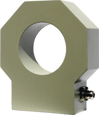
Model TCT-N,
Model TCT-N-HV and Model TCT-N-XHV
Toroidal Current Transformers
 |
 |
 |
|
|
|
|
|
|
|
|
|
|
|
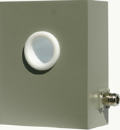
The TCT-N-HV transformer is assembled in an aluminum enclosure with a 3.38" diameter clearance hole for the antenna conductor. This large clearance enables operation with conductor voltages as high as 28 kV peak (20 kVRMS). A 0.75 to 1.0" diameter tubular conductor centered in the clearance hole provides maximum voltage capability. Corona rings which increase the TCT-N-HV voltage rating by approximately 5% are available as a factory installed option.
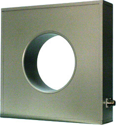
The TCT-N-XHV transformer is assembled in a rectangular aluminum enclosure with a 6.0" diameter clearance hole for the antenna conductor. This large clearance enables operation with conductor voltages as high as 60 kV peak (42.4 kVRMS). A 2.0 to 2.25" diameter tubular conductor centered in the clearance hole provides maximum voltage capability.
Several versions of the TCT transformer are available for different RF current sampling requirements. The TCT-1, TCT-1-HV and TCT-1-XHV transformers provide 0.5 VRMS across a 50 ohm external load for each Ampere of current flowing in the antenna conductor. These models are rated for currents up to 40 ARMS. The TCT-2, TCT-2-HV and TCT-2-XHV transformers provide a 0.25 VRMS/Ampere sample across a 50 ohm external load and are rated for currents up to 80 ARMS. The TCT-3 and TCT-3-HV transformers provide a 1.0 VRMS/Ampere sample across a 50 ohm external load and are rated for currents up to 20 ARMS. The TCT-4, TCT-4-HV and TCT-4-XHV transformers and the TCT-5, TCT-5-HV and TCT-5-XHV transformers are high output, unterminated units which are used only with the 5, 10, 5/10, 5/20, 10/20 and 10/40 Ampere TCA RF Ammeters and with the 10 and 20 Ampere DTCA Digital RF Ammeters. The TCT-7-HV and TCT-6-XHV transformers provide a 0.125 VRMS/Ampere sample across a 50 ohm external load and are rated for currents up to 160 ARMS.
The TCT-1 and TCT-2 may be used in the same directional antenna system since they have identical phase and magnitude tracking characteristics. The TCT-3 transformer has different characteristics and should not be mixed with the other two models. The TCT-1-HV and TCT-2-HV may be used in the same directional antenna system since they have identical phase and magnitude tracking characteristics. The TCT-3-HV transformer and the TCT-7-HV transformer have different characteristics and should not be mixed with the other models. All TCT-N-XHV transformers may be used in the same directional antenna system since they have identical phase and magnitude tracking characteristics. The TCT-N series of transformers should not be mixed with the TCT-N-HV or TCT-N-XHV transformers due to the differences in the toroid inductors used in each design. Similarly, the TCT-N-HV series of transformers and the TCT-N-XHV series of transformers should not be mixed with the other series of transformers due to the difference in the toroid inductors used in each design.
| Model: | TCT-N | TCT-N-HV | TCT-N-XHV |
|---|---|---|---|
| Frequency Range: | 0.5 to 2 MHz | 0.5 to 2 MHz | 0.5 to 2 MHz |
| Sensitivity*: (Volts/Ampere) |
TCT-1: 0.5 TCT-2: 0.25 TCT-3: 1.0 TCT-4: 1.0 TCT-5: 2.0 |
TCT-1-HV: 0.5 TCT-2-HV: 0.25 TCT-3-HV: 1.0 TCT-4-HV: 1.0 TCT-5-HV: 2.0 TCT-7-HV: 0.125 |
TCT-1-XHV: 0.5 TCT-2-XHV: 0.25 TCT-4-XHV: 1.0 TCT-5-XHV: 2.0 TCT-6-XHV: 0.125 |
| Source Impedance: | 50 Ohms | 50 Ohms | 50 Ohms |
| Current Range: (Amps) |
TCT-1: 0 - 40 TCT-2: 0 - 80 TCT-3: 0 - 20 TCT-4: 0 - 20 TCT-5: 0 - 10 |
TCT-1-HV: 0 - 40 TCT-2-HV: 0 - 80 TCT-3-HV: 0 - 20 TCT-4-HV: 0 - 20 TCT-5-HV: 0 - 10 TCT-7-HV: 0 - 160 |
TCT-1-XHV: 0 - 40 TCT-2-XHV: 0 - 80 TCT-4-XHV: 0 - 20 TCT-5-XHV: 0 - 10 TCT-6-XHV: 0 - 160 |
| Absolute Magnitude Accuracy: | ±2% | ±2% | ±2% |
| Absolute Phase Accuracy†: | TCT-1 & TCT-2: ±2ş TCT-3: ±3ş |
TCT-1, -2 & -7-HV: ±2ş TCT-3-HV: ±3ş |
TCT-1, -2 & -6-XHV: ±2ş |
| Magnitude Tracking Accuracy: | ±1% | ±1% | ±1% |
| Phase Tracking Accuracy†: | TCT-1 & TCT-2: ±0.5ş TCT-3: ±1ş |
TCT-1 & -2-HV:
±0.5ş TCT-3 & -7-HV: ±1ş |
TCT-1, -2 & -6-XHV: ±1ş |
| Insulation: | 14 kV peak (10 kVRMS) Optional TCA-LS-8 or TCA-LS-11 line section increases voltage rating to 21 kV peak (15 kVRMS) |
28 kV peak (20 kVRMS) Optional corona rings (standard on TCT-7-HV) increase voltage rating 5% |
60 kV peak (42.4 kVRMS) |
| Electric Field Rejection: | >100 dB | >100 dB | >100 dB |
| Dimensions: (W x H x D) Inches cm |
5.25 x 5.75 x 2.25 13.3 x 14.6 x 5.7 |
6.25 x 7.25 x 2.25 15.9 x 18.4 x 4.7 |
12.75 x 12.00 x 3.00 32.4 x 30.5 x 7.6 |
| Weight: Pounds kg |
3.5 1.6 |
5.5 2.5 |
17 7.7 |
| Order Numbers: | 923-0001-00N where N = 1,2,3,4 or 5 |
923-0003-00N where N = 1,2,3,4, 5 or 7 |
923-0004-00N where N = 1,2,4,5 or 6 |
| * When terminated in external 50 ohm load. Other sensitivities and corresponding RF Ammeter current ranges available on special order. | |||
| † The
Model TCT-4, TCT-5, TCT-4-HV, TCT-5-HV,
TCT-4-XHV and TCT-5-XHV toroidal current transformers are supplied only
with the Model TCA-5, -10, -5/10, 5/20, 10/20, and 10/40 RF Ammeters
and with the Model DTCA-10 and -20 Digital RF Ammeters and are not
characterized for absolute phase accuracy and
for phase tracking accuracy. |
|||
| Delta Electronics, Inc. 5730 General Washington Drive P. O. Box 11268 Alexandria, VA 22312 |
Phone: (703) 354-3350 U.S. Toll Free: 1-800-8-DELTA-8 (1-800-833-5828) Fax: (703) 354-0216 www.deltaelectronics.com Email: sales@deltaelectronics.com |
| HOME | AM/FM/TV Products | HF/VHF/UHF Products |