Model OIB-1
and Model OIB-3 Operating
Impedance Bridges
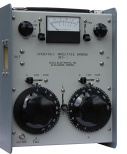
| Model OIB-1 Operating Impedance Bridge |
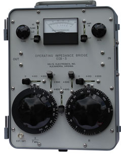
Model OIB-3 Operating Impedance Bridge |

| Model OIB-1 Operating Impedance Bridge |
Model OIB-3 Operating Impedance Bridge |
The
Operating Impedance
Bridge connects directly in series
with the transmission line, network, or antenna. The transmitter power
is applied and a bridge balance is obtained by manipulating the R and X
dials on the front of the bridge. A null reading on the front panel
meter indicates bridge balance. Operating resistance and reactance are
then read directly from the bridge dials. The bridge can also be used
with the Delta RG-4B
Receiver/Generator
or
other receiver/generator equipment to make impedance measurements. The
bridge has been accepted by the FCC for measurement of license common
point impedance. Application
Bulletin No.1 and Application Bulletin No. 3 describe additional measurement capabilities of the Operating Impedance Bridge.
The Model CPB-1, CPB-1A and CPB-1B Common Point Impedance Bridges are similar to the portable Model OIB-1 and OIB-3 bridges, but are designed for permanent installation in the phasing equipment at the antenna common point.
| Frequency Range: | 500 kHz to 5 MHz |
| Through Power Rating | 5 kW modulated; 10 kW carrier only, with VSWR 3:1 |
| Insertion Effect: | Equal to 9 inches of 150-ohm line |
| Functions: | |
| OIB-1: | Direct reading in R, -400 to +400 ohms Direct reading in X, -300 to +300 ohms at 1 MHz Measures VSWR, Zo = 0 to 400 ohms Indicates relative forward and reflected power |
| OIB-3: | Direct reading in R, -1000 to +1000 ohms Direct reading in X, -900 to +900 ohms at 1 MHz |
| Accuracy: |
R and X, ±2% ±1 ohm. Dials individually calibrated and engraved. For high reactance to resistance ratio, the resistance accuracy is reduced. A correction equation and curve is supplied for these high Q measurements. |
| RF Source: | Transmitter, transmission line, etc., or signal generator with adapting connector |
| Detector: | Internal for high power source. BNC connector on front panel for external detector when used with signal generator. For the OIB-1, an amplifier for the internal detector is available as a factory installed option. For the OIB-3, the RF amplifer for the internal detector is standard. |
| Terminals: | Input and output are large UHF receptacles (UG-357/U). Standard 18" input and output clips supplied with bridge. Optional 12" leads at no extra cost when specified with order. |
| Accessories: | MJ-50 Meter Jack BP-50 Bridge Plug Connector Adapters: |
| Large
UHF to BNC
Female (D81-13-1) BNC Female to N Male (D81-76-1) BNC Male to N Male (D81-76-2) Large UHF to N Female (D81-77-1) N Male to UHF Female (D81-100-1) |
|
| Dimensions: | OIB-1: 12-1/2" wide by 9-1/2" high by
5-1/4" deep OIB-3: 13-1/2" wide by 10" high by 8" deep |
| Weight: | OIB-1: 10 lbs OIB-3: 15 lbs |
| Order Numbers: | OIB-1 w/18"
Leads:
920-0001-001 OIB-1 w/12" Leads: 920-0001-002 OIB-3 w/18" Leads: 920-0006-001 OIB-3 w/12" Leads: 920-0006-002 |
| Delta Electronics, Inc. 5730 General Washington Drive P. O. Box 11268 Alexandria, VA 22312 |
Phone: (703) 354-3350 U.S. Toll Free: 1-800-8-DELTA-8 (1-800-833-5828) Fax: (703) 354-0216 www.deltaelectronics.com Email: sales@deltaelectronics.com |
| HOME | AM/FM/TV Products | HF/VHF/UHF Products |